
In this article i shortly describe how to turn your DGT3000 into a DGTPi. Please be aware that if you make a mistake in your cabling you can destroy your DGT3000 or/and your Raspberry Pi. This article is therefore without any guarantee of any kind. Use this on your OWN RISK. You have been warned!
What i describe here is how we developers setup a DGT-Pi during it was not available around November 2015. Perhaps nowadays you can even have a Raspberry Pi Zero inside the DGT-3000 directly. But that needs abit more technical experience. Lets make it easy first.
The advantage for DGTPi is that it directly communicates with the Raspberry over I2C instead of using the board. That makes it alot quicker. Also you can enjoy the full 11 digits of the chess clock. Before you begin please check your DGT3000 firmware version. Press + and – at the same time when the clock is paused and it should say “2.02 B150409” – if it saying 2.00 or 2.01 you need to update the chess clock firmware first to make this work – please talk to DGT then – i cant help to update the clock firmware.
Howto setup the I2C connection with the DGT-3000 chess clock
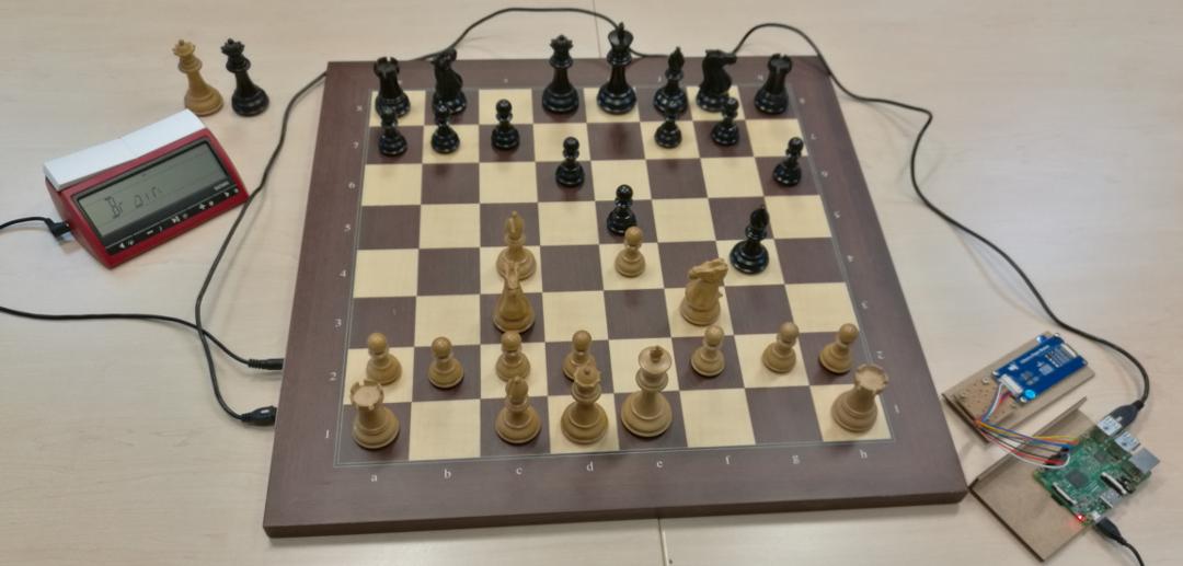
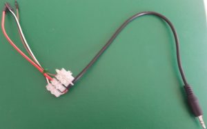
You can connect a Raspberry Pi directly to a DGT3000 by using a standard 3 wire jack plug and connecting it to 5 pins on the Raspberry. Do not plug the jack into an E-board as they work on 5V which the Pi can’t handle.
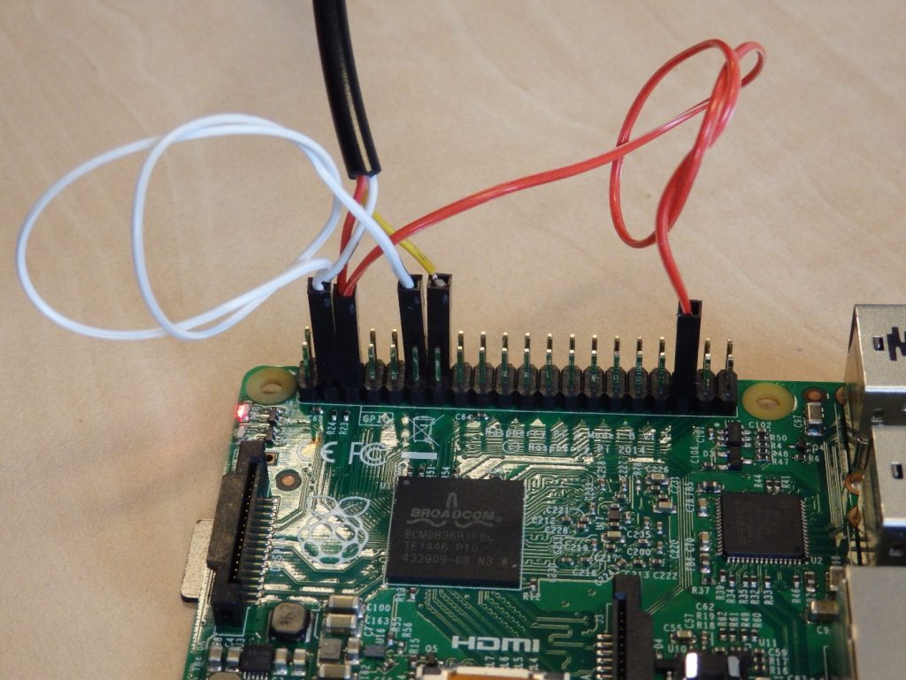
- The base of the jack is ground and needs to be connected to one of the ground pins of the pi. For Example pin 14.
- The second connection of the jack is SDA and needs to be connected to both the I2C master and I2C slave SDA. These are on pins 3 and 12.
- The tip of the jack is SCL and needs to be connected to both the I2C master and I2C slave SCL. These are on pins 5 and 35

So far the cabling. Now the DGT3000 is directly connected over I2C to the Raspberry Pi. The board is connected like before (over USB or Bluetooth). For the picochess software, you need to tell it to use the “dgtpi” flag. This flag will let picochess communicate over I2C instead of using the board. Thats all you need to change from software – but if you don’t it won’t work. Please also be careful, if you change this in your picochess.ini file, you must be sure, you won’t use this image anymore for a standard DGT3000. If you return, you must also deactivate this dgtpi flag.
If you did all correctly, the next startup of picochess using the quick direct connection so you have something similar to a sold DGT-Pi. Enjoy!
Looks great!
Does this enable the same digits/display on the DGT3000 as they are on the DGT PI(number of characters)?
Hi Volker,
yes, there is no difference to a DGTPi, means you would also have 11 (useful) digits.
Very good description, thx – worked for me,I did not know that the solution was that simple. The Next week I try to integrate a Pi nano w into a DGT 3000 clock.
Hi Marion,
thats great. If you done with your nano-W, perhaps y can send me some (inside) pictures for updating this side?!? Good Luck.
Thanks for this hint, Jürgen! I’d like to try and turn my DGT3000 into a DGTPi, too. What kind of cable should I order? I’m not at all familiar with the world of cables and connectors…
Hi DirkJan,
I dont know the names either (esp. not in english). I took them from a local electronic selling shop and connect it with this white “Lüsterklemme”. Sorry.
Hi DJ,
I used these: https://www.amazon.co.uk/gp/product/B01MAXWQHR/ref=oh_aui_detailpage_o01_s00?ie=UTF8&psc=1
3 different types x40 of each.
Al.
Some Pictures of my implementation:
https://goo.gl/photos/uu9dMUbhgs5qVLUR8
Volker
Hallo, can you send me a pictures with Detail of Cabel-Connection.
After this i put CD-Card with Picochess 0.83 to have no Problems with .ini.
Hi Peter,
What exactly is unclear to you? Maybe i can improve the docu – this way – too.
Hello Jurgen. I want to build my Rasberry 4b into the DGT 3000. Have 6 cables. Red-blue-yellow-black-gray-white. Which PIN do the cables come to? Greetings Peter
Im sorry, Peter. Im very very busy right now.
Thats not too easy (for sure, it can be done). The only hint i can give y right now is: Take a look in the picochess forum.
You also need the new version from Lucas of his SO-Lib Files (prob. also can be found on forum).
Hi Chess-Fans,
the modification to a DGTPI-Clock works fine.
The Clock is now faster, and i have now 11 Digits on the Display.
Very nice to play with the “new” Clock.
And i think it is not so difficult to made for everyone.
But watch out which Color of the Cable belongs to the Tip of the Jack-Plug for example.
Use preferably a Electronic measurement to find the right cable.
Here 3 Pictures:
http://www.bilder-upload.eu/show.php?file=f66293-1499878976.jpg
http://www.bilder-upload.eu/show.php?file=36d045-1499879021.jpg
http://www.bilder-upload.eu/show.php?file=3569ac-1499879043.jpg
Thx to Jürgen for the Documentation.
Greets Stefan
Hey Jurgen,
Do you have the communication detail to DGT 3000? I know about I2C communication, but I don’t have the e-board. Would like to try to connect to DGT clock via an embedded demo boards etc just to experiment.
Thanks.
WH
Hi WH,
you can take a look in the “dgt” folder for various files esp. pi.py , board.py and in the “test” folder for the H-file.
The I2C communication is done from the dgt so-lib in “etc”. The sources you can find under jromang/dgtpi in github.
Hope that helps,
Jürgen
Hi Jurgen, thanks very much for the pointers. I appreciate it.
Juergen
Can you please help. My DGT PI board went out. When I took the PI apart the six wires from the clock to the board came out. Do you know the pin out. There is a yellow, white, red, green, blue and black wire. The come from the 1/4 jack and need to plug in to raspberry board.
Hi Tom,
im not sure, i understand you correctly. You opened your (buyed!) DGTPi, and found 6 cables, not connected?
Mainly DGT can answer this. Well, i can ask them, if i get a chance…Can take abit time (right now).
Lucas from DGT answered you already in the other post.
Here is his picture in case you still have problems.
Hi Jürgen,
this is a nice and easy DIY indeed (and again makes me wonder about the type of collaboration between picochess and DGT 😉 ) I’m gonna do this with a PicoZero, I wanna see if the I2C type communication fixes my issues. I think(!) the space should be sufficient to fit the Zero board into the clock. Power has be to external I guess (no room for bats), but this is not an issue. For now, I plan to just turn the mini circuit board with the 3.5 jack by 180deg. This should allow a USB power cable to pass through the hole already present in the clock case and connect the 3.5 jack “internally”. One additional hole on the other side of the clock for the USB-to-board cable and I should be set — damn, I should have scraped the cash for the BT board, than I would not need an extra hole in the case 😉 Anyways, later I might go for some nice plugs instead of dangling cables once I got this to work.
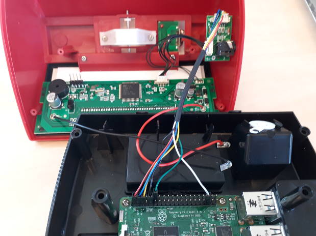
I have a question concerning a “final design” if indeed the Zero board fits inside the clock case: Looking into the interior of my clock I think the simplest way of connecting Pi and clock might be directly via the 5 point mini-plug directly next to the 3.5 jack leading to the clock-board as this can simply be unplugged (left hand side in the above pic). Do you by any chance know the pinout of this plug and/or the according sequence for the I2C pins? Because then the 5 wires from the GPIO pins could directly be connected to the clock via this (compared to a 3.5 jack much smaller) connector.
And yet again: thanks for your time and efforts you put into PicoChess!
cheers,
Jack
Hi Jack,
a zero should suit inside and y might connect the cables similar to dgt’s way (internally).
For your answer (pinout’s) please wait a few days.
In meantime, y can take a short look in the http://picochess.com/dgtpi-advantages-part-1
post for Lucas answer.
Hi Jürgen,
while waiting for my PI zero to arrive, I soldered together a cable to use with my current PI3 to test the general setup. The I2C interface is really great compared to the ‘via-board’ communication, nice speed – much snappier!
I just have one issue/question: I had a small touchscreen attached to my PI up to now, but this also used the GPIOs, so I had to remove it and now enabled the picochess services to control the PI.
My question is: What is the right “combination” of services with this DIY DGTPI? Using the DGTPI services hangs picochess already at startup. Using the picochess service ONLY will not shut down the pi and copying the dgtpi-ones in addition makes shutdown with two queens work, but the PI seems to reboot several times before it really shuts down: I see the “PICOCHESS version 0.9d” and “Goodby” message several times, until the pi finally is really down.
How to do this properly?
Hi Jack,
please take a look here:
http://docs.picochess.org/en/latest/installation.html (esp. point 6+7)
Your system crushes when exactly (1.sentence) ? Im sorry, i cant follow all.
Hi Jürgen,
it does not crash at all, it just reboots twice before finally shutting down. But thats only a minor issue! I’ll look into the service files once I’m done with the hardware.
I just finished my first game against Stockfish 8 on my brand-new RasPi Zero using the DgtPi setup. Now the zero has only to find its place inside the clock…
update from my side: I got my Zero inside the clock working.
I’m using the 5pin plug on the mainboard of the clock for the connection to the Zero and actually removed the small board-piece with the 3.5 jack completely to gain some space for wires.
The pinout of the plug is actually very simple:
PIN 1 (red): Ground
PIN 2 : GPIO 5/35
PIN 3 : GPIO 3/12
PIN 4 : Ground
PIN 5 : Ground
Just some further thoughts on this:
– one might think of powering the clock via the PI. Using the 3V GPIOs “kinda” works, but these do not provide enough power. The “low bat” sign of the clock is on all the time and the display is quite dim => this would require a step-down connected to the 5V pins, which could be easily done.
– the reverse, powering the PI from a bat would also be an idea, but stepping-up the 3V from the clock bats would probably not last very long. Putting a LiPo inside the case might be a really tight fit and probably a stupid idea, anyways.
– I’m working on a MARKII of my setup involving my original Pi3. I’m gonna report back in case I get this working as well.
Hi Jack,
i talked shortly to DGT and they replied as following:
When you supply using 3v on the jack the battery icon always turns on ( if you take out the batteries)
The pi can easily supply power enough power for the clock.
The clock has an boost regulator, so it can work on any voltage between 2v and 3v on the battery terminals or supplied through the jack. you can also directly supply 3v3 to the right pins
In any case power should not be low, you can however have the battery icon turned on if you don’t supply to the battery terminals
Hope that helps.
hm, thanks for the info – that sounds interesting. For my tests I removed the clock bats and attached the 3V of the Pi GPIOs to the terminals on the back of the bat housing. If DGT says this is OK, then I might do it this way. The max power these pins provide is difficult to find on the web explicitly – many, many different opinions…
I will do some further testing as I’m still waiting for a part for my “MARK II” project to arrive before I fix my final design.
But in fact I am quite happy with my current “PicoPi” – even though the difference in speed between the zero and the Pi3 is quite massive.
Here we go, the base for my new PicoPi just arrived from the 3D printer:
http://www.bilder-upload.eu/show.php?file=705942-1504129834.jpg
Hi Jack,
very nice work! is it possible to get the .stl file of this case ? i’m realy interesting 🙂
Thanks,
Eric
Hi Eric,
yes, no problem. I’ll upload the stl or I’ll post the tinkercad-link. But be warned, the model has two small bugs: the holes for the rear plugs are 1-2mm too far to the side of the USB plugs and the wall is too thin for ABS, it is actually flexible. But the rest is OK.
OK, here is the tinkercad link:
https://www.tinkercad.com/things/26EQFegGT5e-picopi-base/editv2?sharecode=huHbEI-QEAbUQ1KWuU-RICJqXJ45sm7LHUcQ5F6eHPs=
Disclaimer: This was my very first 3D model ever. I am providing the model as is, fit for nothing and without any guarantee that it is useful for anything. So you have been warned: It may eat any DGT3000 or PI it gets in touch with.
And just in case this still did not scare you away, here are some notes if you plan to use the model as is:
1. Make the BACKSIDE thicker! The rest is OK, just the backside with the power/display/headphone is TOO THIN => Make it as thick as the front/left/right part.
2. There is a small shift in the backside holes for the plugs, nothing you could not fix by a rasp.
3. The four tube-like holes fit the outer screw-holes of the clock case.
4. The four larger holes were made for the rubber feet of the original base of the clock case. They are a tight fit, so some polishing is needed here after printing, but I would not really make them larger.
5. Mainly due to its size I guess, this model is not really cheap to print. I had it printed in ABS (see pic above) and this shipped for approx. 40€.
6. Just in case you fix the above issues: please share the update, I might re-print mine with some further add-ons later, once I decided on how to power the whole thing (internal LiPo vs. external power bank?).
cheers
Jack
P.S: my Raspi3 died on me – well not entirely, the Wifi is dead (hardware wise as it seems, although Bluetooth is stull operational – strange). I’m therefore using my Zero inside the case atm.
Thanks a lot Jack 🙂
A friend of mine have a 3D Printer and we’re going do try printing it.
Ok for the advice on the thin backside, i hope my friend can modify the scheme on Tinkercad.
Sorry for my short answer, english is not so easy for me lol 😉
Cheers,
Eric
Hi Jack,
Can you re-upload this?
The link is expired. 🙁
Much appreciated!
Michel
OK guys, I finally completed my PicoPi.
I’m now using the 5-pin plug to power and drive the clock via the Raspi3 which is sitting in the case I showed above. It nicely fits underneath the clock so that the whole thing looks much like the original DGTPI.
Concerning the wire-up I now can complete what I wrote above,
the 5-pin plug can indeed also power the clock:
RED
—————————–
| 1 2 3 4 5 | 5-pin connector from the 3.5 jack
—————————–
6 5/35 3/12 1 6 RASPI GPIO pins
3.3V
This way I can remove the bats from the clock with just one downside as Jürgen wrote above: the low bat sign is now ON all the time (but so what).
So this is now more or less my final design, I think I’ll just add a LiPo to power the whole thing as I have now the space for the LiPo and the charger/booster board in the base.
Is the STL file still available – I have a 3d printer and would like to print my own.
Hi Ray,
i dont have his STL and i guess he not reading yr text here (anymore). Perhaps y should eMail him directly?
Hello Jurgen.
Thank you for the reply, I finished the DGTPI setup this morning and all works fine, I may have a go at designing the base cover for the 3000 clock and get it printed, it would have been easier to modify an STL file than start from scratch. I don’t have the chaps email address so I was hoping the reply to his post may get forwarded onto him?
Do I have to use the DGT Pi Image after the conversion, or the Raspberry?
Cheers Ingo
Hi Ingo,
after successful change the dgt3000, y need to use the dgtPI image.
Please post in english ONLY. thanks.
Jürgen
Hello Jürgen, thank you, now I wait until all components are here, then I post if everything worked out.
Cheers Ingo
Hello. Great topic. I have one question though: Is there any difference in terms of speed (response from the clock) if using Raspberry Pi Zero vs the usual Raspberry Pi? I know the technical differences between the 2 Raspberry boards, but in real life with picochess do you sense some delays with the Zero board? Thank you
Hi guys,
Jürgen informed me, that there is still interest in the case I posted earlier.
Here you go, a fresh TincerCAD link:
https://www.tinkercad.com/things/d9BqKPQl9q9
let me remind you of the warnings I mentioned above, be prepared to do some finishing of the printed case by hand. This link is a mark 2 of the case with the most severe bugs fixed, but I still can not guarantee a 100% fit.
And just some heads up on my design: I now fitted the Raspi3 into the original clock case with just two holes made for the power and USB-board connector. For a BT board you would only need one hole. So in short I’m not even using this case anymore to be honest but have a PicoPi which looks like a DGT3000 clock.
Hi Jack, Thanks a million!
Will try to get this printed asap.
Wow, you managed to get the Pi3 in the clock? How did you connect, by a jack going outside the case back in or did you rewire inside?
It must have been a tight fit, I could manage a pi zero W in, but this was definitely to slow for a nice game.
Will also try to get the 3 in, just because it (obviously) can. 🙂
Hi is it possible to have the .stl file?
I don’t know if on Tinkercad we can upload it?
Thanks
Hi,
No problem hope you can use the design. And no wires outside, I went the internal route directly. To fit the Pi3 in I took the step to remove the battery case bulge on the inside of the bottom plate of the clock, as power for the clock is also provided via the Pi.This creates the space to fit in the Pi3 and fix it via screws to the clocks base plate. One new hole in the back of the case for the USB power and an extension of the 3.5 jack hole with the jack removed did the rest. Pics on demand ?
cheers,
Jack
Hi Jack, If you have some pics to share would be great. Especially the wiring you did inside would be very helpfull.
Hi,
I’m gonna post some pics later, for now: the wiring is based on an old IDE HDD cable for the GPIO Raspi-GPIOs, to which I soldered wires of the micro connector which originally connects the 3.5 jack “board” to the mainboard of the clock. I actually bought a new plug (5 for just a few euros) off ebay (so I can “go back”, i.e. unplug the PI and re-fit the jack if needed). You can get these plugs with wires already crimped in, so it was just a matter of soldering the right IDE-cable wires to these pre-fixed wires of the plug (search for something like “Micro Mini JST GH 1,25 mm 5 Pin”).
The final pinout is given above in my comment from September 1, 2017 at 10:51 pm. This also powers the clock via the Pi and lets you remove the bats from the clock as described above.
In my case the whole thing is powered via an external USB power bank. The one I’m currently using does not fit my “PicoPi case” design (the power bank is actually as long as the clock case but therefore one full charge lasts forever 😉 ), but some day I might get a smaller one and put the bat into the case.
cheers
Jack
ok, here we go. I took several pics to show off the hole thing 😉
first a test with thumbnail (dunno if picochess.com can handle this):
admin: not working link removed
In detail as links to be save:
back => USB power cable for Pi and clock:
admin: not working link removed
bottom => you see the four mounting-screws fixing the Pi to the base of the clock and the Pi through the battery slot (I removed the bat-cover of the case for taking the pic):
admin: not working link removed
updating => yes, there is a working Picochess-Pi in there 😉
admin: not working link removed
left side of the clock, showing the “extension” of the 3.5 jack hole
for the USB DGT board connector:
admin: not working link removed
Opened up. you see the Pi with the IDE connector on the GPIOs, the wires trimmed and soldered to the colored wires of the micro-plug. There are some spare wires taped to the from side of the Pi, these could be used to power the whole thing from a power-bank in the PicoPi case as future option. The black “spiral” to the left is the rest of the USB connector wire for the board-plug.
admin: not working link removed
USB plug internal => this is a cheap USB cable I had lying around, I did not want to shorten/re-solder it, so I wound it up into the above mentioned spiral (yeah, I’m lazy and wanted finally to play some chess):
admin: not working link removed
this is the plug I got off ebay for soldering it to the IDE connector:
admin: not working link removed
That’s it, hope this helps to build your own PicoPi3. BTW: Just in case you wonder why to use the “bulky” Pi3 instead of the Pi zero: the zero is tooooo sloooow for Picochess IMHO!
cheers,
Jack
Damnit, all links seem to be dead after posting the reply?!?
reup, (hopefully) in the same order as above:
https://picload.org/view/ddiwgori/back.jpg.html
https://picload.org/view/ddiwgorw/bottom_battery_hatch_removed.jpg.html
https://picload.org/view/ddiwgodr/front.jpg.html
https://picload.org/view/ddiwgoar/updating.jpg.html
https://picload.org/view/ddiwgoaa/usb_board_plug.jpg.html
https://picload.org/view/ddiwgodl/internals.jpg.html
https://picload.org/view/ddiwgoda/ide_plug_with_spare_wires.jpg.html
https://picload.org/view/ddiwgodw/raspi3_on_base.jpg.html
https://picload.org/view/ddiwgoal/usb_plug_internal.jpg.html
https://picload.org/view/ddiwgodi/micro_plug_mainboard.jpg.html
Hi Jack, thanks again for all the effort! I will enjoy the new clock shortly I hope.
One other question, do you know if, when wirering all insight you can stil connect the board when playing Fritz?
And indeed, the zero is way to slow to get picochess running nicely.
Hi Michel,
I dont think this will work via I2C. Jürgen might have the final word here (I dont have a Windows PC to test this), but I guess Fritz will need the ‘through the board’ communication and you have to use the 3.5 jack to connect the clock to the board.
Therefore, you would need to make the I2C/external communication switchable somehow.
cheers,
Jack
I dont use win$dows at all, sorry. and somehow my keyboard is broken, as soon i write “win$dows” it always put a US$ sign inside 🙂 Can someone help me?
The problem is not the software, its the hardware. You need a hardware to allow a standard pc to communicate over i2c with the dgt hardware. If y have such card and a driver for a special os system (ha, tricked out my keyboard) fritz might be able (after software update) to talk to a dgtpi clock directly.
Hi Jurgen
you spoke about the firmware of the clock.What’s problem if the firmware is start by 2.01?
Thanks in advance.
Best regards
where? please more details 🙂
Hi Jurgen
you explain at the beginning that the firmware of the clock must start by 2.02 and not 2.00 or 2.01.My clock has 2.01 so it’s can’t work?
After the modification by DGT ,I need to burn another image DGTPI to work?Is it correct?
Thanks
yes, y need to send yr clock to DGT to update the firmware. Updating an old (firmware) dgt3000 clock wont work. Then y can change the hw as described and take a DGT-Pi image to make it work.
Thanks a lot for the request and “Bravo” for your work.
Best
Hello guys
I did the modification to get a DGTPI clock and it’s work but with a connection USB.I don’t know how to get the bluetooth?I use a image v09i.If somebody can help me?
Thanks
Youen
I replaced the Raspberry Pi inside the DGTPi with a new RPi 3B+ (using the latest Raspbian) and reconnected the wires to the same pins as before. Sadly, this does not work.
When I put the old RPi 3B back inside, using the very same Raspbian, the DGTPi functioned correctly again.
Anyone have an idea how the wires should be connected on RPi 3B+? Or is some software setting required?
I just attempted the same thing an hour ago myself. Same issue. Any help would be appreciated. 3b+ is not powering on.
So I noticed that the included power supply for the dgt pi is only 2 amps. Bought a 2.5 amp one and now it powers on, but I get the 4 slow and 4 fast blinking lights. I need to update the sd card before I can get it to work.
Hi DJ & Jason,
I can’t start looking at the new RPi until next Monday when I’m home but 3 things spring to mind:
1) if the new is really 64 bit is there a new operating system?
2) do I need a better power supply?
3) will I need to create an armv8l directory and copy the armv7l engines into it?
See you all from Monday
Al.
Hi Jason,
Thanks for your reaction. I’m using the original Raspberry Pi 2.5A power supply instead of the 2A power supply that came with the DGTPi. It makes no difference here.
The problem seems to be that pin 12 (GPIO 18) is not being set to “alt3” mode on the new RPi3B+ in the same way as it was on the old RPi3B. The dgtpi.service script is failing at startup with error code 246 and the PicoChess log has an error message about the jack not being connected.
Greetings,
DJ
Hi DJ & Jason,
to make Pi3+ work the same way as Pi3 i cant help y. I think, y need to ask Lukas for it since he also dev’ed the SO file.
All working now, thanks Lucas, DJ & Jürgen …
Cheers,
Al.
Hi
If somebody want I can sell a câble for the DGTPI.
Best
Hi Al,
would you mind sharing how you got it working on the Pi3+ ?
I ran into this issue just today.
Many thanks and kind regards,
Patrick
Hi Patrick,
take a look here:
https://github.com/jromang/picochess/issues/272
Hi Jürgen,
thank you very much for your quick reply, it seems to be working now!
But sometimes the clock hangs or does not register when I press buttons, with dgtpi showing afterwards:
root@DGTPi:/opt/dgtpi# ./dgtpicom
I2C Master might be stuck in transfer?
FIFO=30
C =0
S =50
DLEN=0
A =8
FIFO=8
DIV =a47
SDA=0
SCL=8
-> 10 20 06 0b 39 b9 = Change State
170.450 Send error: Bus free timeout, waited more then 10ms for bus to be free
SDA low. Remove jack?
170.450 sending mode25 command failed, sending failed
Could this be faulty hardware on my side?
Kind regards,
Patrick
Hi all,
just to solve my last reply, if anyone else is seeing similar issues:
I had to redo my cable work and use a 4 pin 3,5mm audio jack for the DGT 3000 clock, it seems that my salvaged 3 pin connector did not match the contacts in the clock exactly and shorted out the i²c bus.
Again many thanks to Jürgen for pointing me in the right direction, I could not have successfully completed this project without your help!
Kind regards and best wishes,
Patrick
Hello fellow readers,
Now I would like to introduce my DGT Pi replica. I installed a Raspberry Pi 3 Model B, a VIVIS 20000mAh powerbank with 2 charging ports and MOBI speakers in a wooden box. The part I operate with a Picochess version 0.9n.
I will be happy to answer any questions. Thank you for the many tips and advice.
Greeting Ingo
https://www.dropbox.com/sh/dkxw2jz42eud8j7/AACgLXw-IVbtUVDECUGwwxR_a?dl=0
I’ve developed a PCB that together with a 5-pin molex connector and cable greatly simplifies the hookup. Also features a slightly improved base (with larger screw holes): http://simplestuffmatters.com/?p=124
Hello:
I am far from being an expert, but I’m trying to make this implementation work, the wiring is very easy, I just got confused with: ‘For the picochess software, you need to tell it to use the “dgtpi” flag2’. ¿How exactly is this done, if you don´t mind?
Many thanks,
Sergio
Hi Sergio,
welcome!
you need to edit the “picochess.ini” file – for example with “nano”. There is a line with “dgtpi = False”, turn this to “True” and remove the “#” like its said on picochess.ini.example. Safe&reboot.
As an alternative y can download a dgtpi-image (for example from this webpage see: images).
Thats more straightforward, but takes alot more time (as only change one line).
Thank you Jürgen, I was able to do it easily. I have now set my DGT 3000
set a DGT Pi, sending pgn files to my email address, awesome!
Thank you for the excellent work, Happy Holidays!
Sergio
Hello,
I’m not very trained in these things. So please excuse me if my question sounds stupid. Is it possible to connect via USB instead of using the pins?
Best regards
Hans
Hi Hans,
y can only use the GPIO pins…not USB to build up the DGT-Pi. Lateron, it behaves like a real DGTPI, incl. the USB port working.
Jürgen
Hi,
can I use an existing dgtpi image (and not picochess) with this setup (so no need to change the flag in the ini file)?
Regards Bernie
Hi Bernie,
yes (but dgtpi IS picochess, ha).
Thanks for saving me $300; works a treat!